Refurbishment of East Sand Filter Drain Valve
One of the necessary tasks, at least once each year, is the cleaning of the Sand Filter Ponds, particularly to remove weeds which grow between the base slabs, and any other organic matter. To perform this task, it is necessary to drain the pond to at least the level in the clean water outlet channel. Over the years, the channel drain valve on the east pond, just behind the Gas Engine House, has become more difficult to operate, hence the decision was taken to refurbish it.
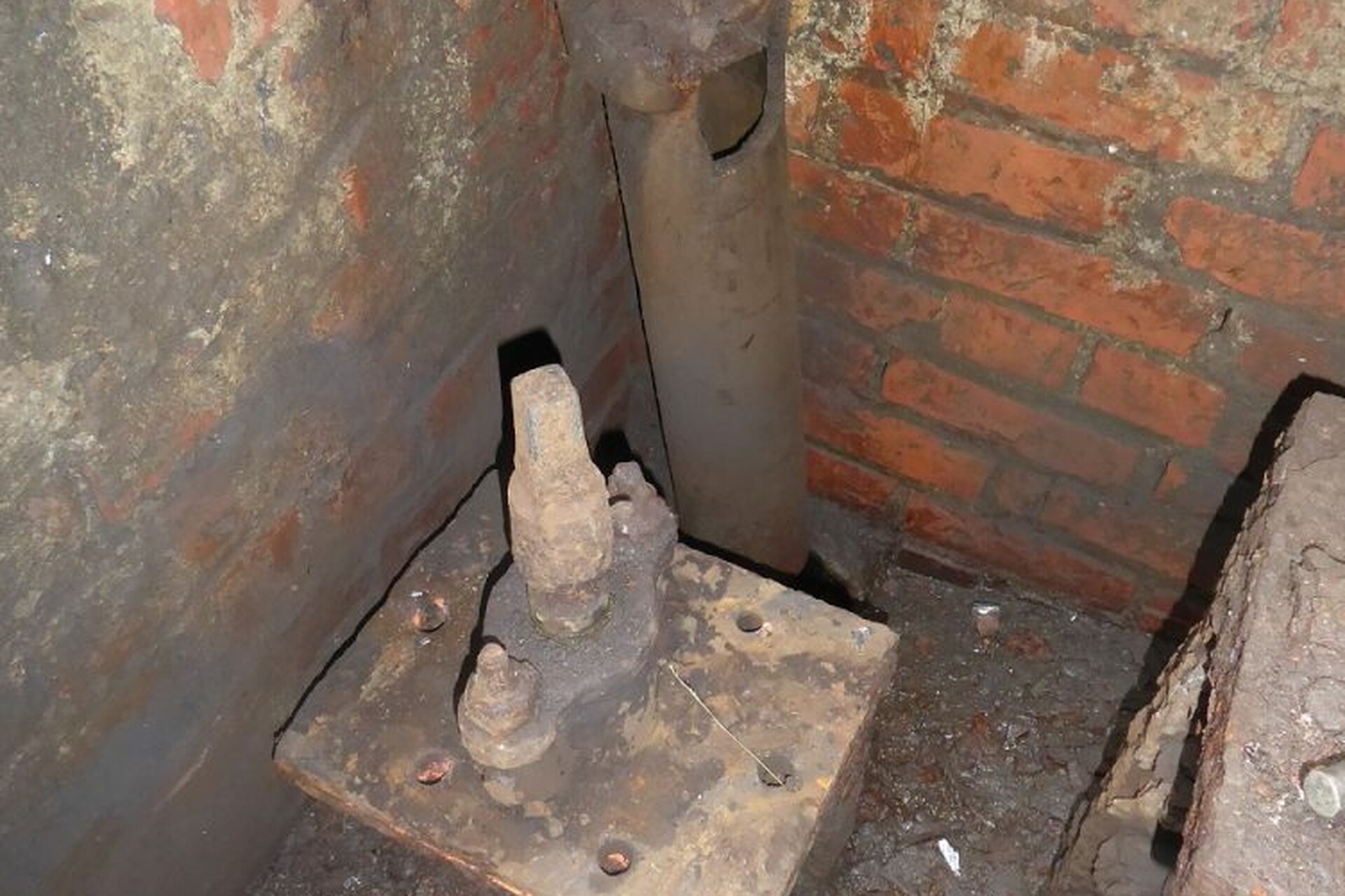
To gain access to the valve, it is first necessary to lift a very heavy, steel, cover plate (a hazard in itself) before looking into the 8-foot-deep brick lined chamber. At the bottom of the chamber are two valves, the 6-inch drain valve and a larger, 18-inch, valve in the line between the pond and the east Clean Water Tank. Both valves looked as though they had never received any attention since their installation in the late 19th century.
The valve is on the left hand side, below the drain pipe, in the photo below.

Lubrication and movement of the drain valve proved unsuccessful in freeing it, so it was decided to strip the valve down and refurbish it. Removing the valve completely was not an option as its inlet and outlet flanges were partially buried in the concrete floor of the chamber. The decision was therefore taken to uncouple the valve bonnet from the valve body and then withdraw the valve spade. The six bolts, attaching the bonnet to the body, were corroded so badly that they couldn't be removed with a spanner and so had to be cut off with a cutting disc. A gas test had already been performed and proved that the atmosphere was safe for breathing and safe from explosion risk. However, it was still necessary to wear breathing apparatus whilst cutting, to avoid breathing in the disturbed dust and rust in this confined space.

Once the bolts had been removed, we discovered that the valve spade was well and truly stuck in position and, although it could be moved in the horizontal plane, it would only move incrementally in the vertical direction. However, a good number of hours later, with the help of chain blocks and an assortment of prising tools, the spade came free.
The spade, bonnet and gland assembly were then taken to the chain store for stripping down, cleaning, and reassembly.

Stripping this unit down required the two gland packing bolts to be removed, again using a cutting disc. These bolts each had a locating lug at one end and two new ones needed to be fabricated.
The valve internals were cleaned and wire brushed in order to more easily facilitate replacement in the valve body and a rubber gasket was fabricated to make a seal between the valve body and the bonnet. The gland seal was repacked with half inch square packing and tightened down.

An interesting feature was the valve shaft. The shaft, has a "two start left hand thread". This means that the shaft has two threads cut into it at 180deg. apart. With two threads, this means that for every full turn, the nut and valve spade assembly raise twice as far, as a single thread. The thread form, as stated above, is Left Hand - most people are familiar with a standard thread form, i.e. Right Hand. When viewed from the side, a right-hand thread raises from left to right and from the top it screws in, clockwise. A left-hand thread, when viewed from the side, raises from right to left and from the top it screws in, anti-clockwise (we believe that it was standard practice to use left hand threads on water valves and right-hand threads on gas valves in the 19th and early twentieth century). One other feature of the thread is that it has a "square" thread profile. Square threads are used in heavy load applications as they are stronger than a normal triangular profile. Since this shaft is made from brass (or perhaps phosphor bronze), it was in almost perfect condition.

The valve assembly was then greased and the externals and internals painted with a protective layer. The valve body was cleaned internally and the bonnet, shaft and paddle reinstalled. After proving that the valve operated freely the new, exposed bolts were wrapped in Denso tape, hopefully to make the next maintenance schedule a little easier.

The final task was to cut a hole in the chamber cover plate through which to access the valve spindle, without need to raise the heavy plate, for future operations.